Positive thoughts about RenderPal

Software:
RenderPal 2.14

Renderpal
Renderpal Server console

Moving from the robustly equipped* Autodesk 3ds max to the pioneering state of Blender, I was looking for a proper studio render management solution.

Blender doesn’t come with a batch rendering / render management solution.
Some notable solutions to that are RenderPilot which is a free and very effective batch render utility for Blender I used extensively (RenderPilot is developed by Wigglyframes),
And Flamenco which is a Cloud/Net rendering management solution for Blender currently in beta development stage.

Flamenco is the formal solution that will be offered by the Blender Institute, along with a cloud service for Blender cloud members.
I’m really interested in Flamenco, not only because I’m a Blender cloud member and can use the Flamenco cloud service, but also because to my understanding Flamenco is capable of sophisticated control of Blender render settings, like the samples range and seed, combining renders with different sample ranges and such.
However Flameco is currently at Beta stage of development, and it’s components don’t yet have friendly installer packages, so you have to install and configure all the components, and their prerequisites manually through command-line using parameters specified in configuration files etc’, a task that’s just too complicated for me especially being in an urgent need to get things running to deliver animations to customers.
That being said, Flamenco and it’s Blender cloud service look very promising and I will definitely give it another try when the package gets proper installers.

So after a quick web search for render management software I came across RenderPal, which is a render management solutions that supports a wide variety of video/animation software systems, and has a fully functional free version.

I registered at the RenderPal website for the free license, installed the software components, and after some learning and trouble shooting I started using the software, eventually purchasing a commercial version.

I find RenderPal to be very efficient render management solution, it’s easy to install, it has good monitoring capabilities, it’s flexible, and can interface with a wide variety of animation / post production software.
I find it’s SMPT mail notifications feature very convenient, and the company also provides responsive tech support when needed.

* Autodek 3ds max ships bundled with Back Burner Net render management software.

Cycles True Displacement (experimental)

Software:
Blender 2.79

These are the steps to activate Cycles Render new experimental MTD feature (Micro Triangle Displacement)

Cycles Render settings:
Set ‘Feature Set’ to Experimental.

MTD_A

Object:
Apply a Subdivision Surface modifier and set it to Adaptive mode.
* Adaptive Mode is only available if the modifier has no other modifiers below it.

Set the ‘Dicing Scale’ attribute in pixels to set the displacement accuracy
* Lower numbers will result in greater details and more memory usage

MTD_B

Material Cycles settings:
Set Displacement to ‘True’ or ‘Both’.
* Setting it to Both will automatically use the same height map texture data to drive surface normals (bump) and create a consistent effect

Displacement set to 'True'
Displacement set to ‘True’
Displacement set to 'Both'
Displacement set to ‘Both’

Cycles material node:
Connect a texture to the Displacement input.

White color will displaced to a height of 0.1 units (10cm) by default, manipulate the texture data using math nodes to achieved desired height and offset.

MTD_D.jpg

Cycles Geometry settings:
For more accuracy reduce the Subdivision pixel rates And increase the maximum subdivisions.

MTD_E.jpg


Notes:

  1. There is currently conflict between Adaptive Subdivision and Tangent Space Normal Maps that renders objects completely black.
    A solution that is proposed at various discussions is to simply use Object Space mode in the Normal Map node.
    I’m not sure how good is this workaround for non flat surfaces..
    https://developer.blender.org/T49159
  2. When using a procedural fractal texture as a Displacement map, Shaders that are dependent on surface angle may significantly change their appearance in different rendering resolutions because the texture provides more and more detail for the displacement and that changes the nature of the geometry.
  3. The base mesh for the Displacement should be well Subdivided prior to the adaptive Subdivision in order to avoid polygon edges appearing.

Cycles Area Light pleasant surprise

Software:
Blender 2.79

One of the features I would really like added to the Cycles Renderer is a photo-metric workflow.
That is the ability to set light sources intensity using real-world photo-metric units, load IES photo-metric data, have a physical daylight system, and set photographic camera exposure and white-balance for the output image.

While Cycles currently doesn’t have a fully functional photo-metric workflow,
It is equipped with some important basic ingredients needed for the development of such a workflow.

One Of these features is the Black-Body color conversion node that allows specifying color by Kelvin color temperature,
Another is the procedural Sky texture featuring Hosek / Wilkie and Preetham physical sky models, that can also be controlled according to global position, date and time with this addon.

Recently I’ve had a pleasant surprize finding out that Cycles actually has another important feature for a photometric workflow, and that is that Cycles Area Lights maintain a fixed general light output (‘Luminous Flux’) while area is changed and changes specular intensity correctly to so that the smaller the light source area, the greater its brightness (as it should physically be).
* This in difference to the way a mesh light with an emission shader behaves where the light output is per area and therefore increases or decreases when changing the shape and size of the surface.

This makes designing light sources with a fixed total output of light yet different shape, and therefore different specular reflection, shading, shadow softness possible,
And is in itself a valuable feature in realistic light source design.
* Especially coupled with setting the light color using Kelvin color temperature (Black-body node)
The only thing missing is the an ability to specify the total output of the light source in Lumens (lm) units.

I have encountered a mentioning of Cycles having a physical scale conversion ratio here:

http://www.3d-wolf.com/camera.html

Marco Pavanello, the developer of the Blender ‘Real Camera Addon‘ wrote:
“In Blender the Emission Node Strength is measured in W/m^2”
I haven’t had the time yet to seriously find out how that should be translated to intensity in lumens..
* It  should be noted that both the Cycles Area light and mesh light use the Emission shader as there source for intensity / color settings, but differently,
You can see in the demonstrations below that for a light source of the same surface area a significantly larger strength value is needed to produce roughly the same light output as the light mesh and this is probably due to the output being internally divided by surface area which is in fact the subject of this post.

Here are some renders to illustrate the point, and the diffrent behavior of light mesh (mesh with an Emission shader)
I’ve added a rough glare effect that depends on float color intensity to illustrate the way the specular highlight intensity increases as the area of the ligt source gets smaller while overall light output is the same:

AREA_Sizes
Cycles Area Light with different sizes but same strength
MESH_Sizes
Cycles Mesh Light using an Emission Shader with different sizes but same strength

MESH_Sizes_Compensation

Cycles Mesh Light using an Emission Shader with different sizes and strength changes to compensate

Controlling shader visibility with Cycles Light Path Node

Software:
Blender 2.79

The Cycles ‘Input > Light Path’ node is useful for creating shaders with a selective optical participation.
A simple example of that would be a bright light material that is ‘seen’ by the camera and through reflection / refraction but isn’t actually lighting the scene.

Basic Ray Visibility can be set at the object level via the object’s Cycles setting:

Ray_Vis

But when we need to set per shader, and more specific Ray Visibility, we can set it up using a ‘Light Path’ node within the cycles shader:

Light_Path

The ”Is ________ Ray” outputs will give a 0 / 1 value indicating if the sampled ray is of a certain type,
The Ray Length output will give a float value representing the ray’s real world length,
And the ‘_______ Depth’ outputs  will give an integer representing the number of light bounces that were computed until the sampled ray.

In this simple example we see how to use the Light path node to create a light shader that only affects reflections / refraction but not producing any diffuse light.

A Mix Shader is used to mix between a Transparent Shader and an Emission Shader.

The ‘Converter > Math’ ‘Maximum’ node is used as a logical ‘OR’ operator to produce a value of 1 for the mix factor if the ray type is either a Camera Ray or a Glossy Ray or a Singular Ray, and cause the Emission shader to be active.
For other ray types the mix value will be 0 and the Transparent shader will be active.

Basic Emission Shader:
Ray_A

Restricted Emission Shader:
Ray_B.jpg

* At the time of writing this post the ‘Is Diffuse Ray’ output of the ‘Light Path’ node didn’t produce expected results so I couldn’t create a light material that creates diffuse lighting but doesn’t  appear in reflections and refractions.


From the Cycles documentation:

Ray types can be divided into four categories:

  • Camera: the ray comes straight from the camera.
  • Reflection: the ray is generated by a reflection off a surface.
  • Transmission: the ray is generated by a transmission through a surface.
  • Shadow: the ray is used for (transparent) shadows.

Reflection and transmission rays can further have these properties:

  • Diffuse: the ray is generated by a diffuse reflection or transmission (translucency).
  • Glossy: the ray is generated by a glossy specular reflection or transmission.
  • Singular: the ray is generated by a perfectly sharp reflection or transmission.

Baking normal maps in Blender

Software:
Blender 2.79

Normal Bake

1) In the render Tab, under ‘Bake’, select Bake Type: ‘Normal’, enable ‘Selected to Active’, and set Ray Distance large enough to cover the geometry.

2) Make sure the target object has an active UV channel

3) In the UV/Image editor, create a new image with the desired resolution, and name it.

4) In the target Object’s material, set an Image Texture with the new image you created, make sure the Image Texture is node selected in the Node Editor of the Target Object’s material view, so it will be the target for the baked texture.

5) In the render Tab, under ‘Bake’, press the ‘Bake’ button.

6) Set the image texture as the materials Normal Map, check if it’s effective and save it to disk.

Lamp_Shaded
Model on the left is a 1.5 million triangle 3D scanning of an archaeological find, Model on the right is a 4000 triangles retopologized low poly model with geometrical details baked into a Normal Map.

Lamp_WIre

Non-Color texture data in Cycles render

Software:
Blender 2.78

When loading texture files into a Cycles Image Texture node, it’s a good idea to take a moment to set the Color Space parameter correctly.
This parameter sets how the color data is intended to be used in the shader, that is, if it will be used as ‘Color’ like a Diffuse texture for example, or as ‘Non-Color Data’ like a Normal map texture example.

NRM_Wrong

NRM_Correct

The reason behind this is that texture data encoded in sRGB color space (JPG, PNG,..) intended to be used as color should be ‘linearized’, that means the gamma correction sRGB files are automatically encoded with should be removed, so the the color data will represent linear color values suitable for the processing of shaders and compositing the final rendered image*,
While texture data intended to be used as data like height or direction or percentage, shouldn’t be linearized, assuming that the colors were saved without adding a gamma corrections to them.

A common example of that is when using a normal map stored in PNG format,
When the Color Space parameter is set to ‘Color’ the resulting bump normal might look wrong, and also display hard edges along UV coordinates seams.
Setting the Color Space to ‘Non-Color Data’ will solve the problem and interpret the bump normals correctly.

> usage of a texture as input for a non-color parameter like displacement will automatically use it as linear color.

> 32 bit float formats like exr are automatically interpreted as linear color by the renderer (the viewport material display will still show a differance so it’s better to set it to ‘Non-Color Data’ anyway).

> It should also be noted that Blender has two parameters controlling the interpretation of an image file one in the Image Texture Node that controls the color usage, one in the Node properties that controls how the file format is interpreted,
And also general color management settings that control the display of colors and saving of image files.

> It should also by noted that I’m still baffled by Blender / Cycles color management.. 🙂

* Linear color is also suitable for post rendering / post production compositing for image development and VFX.

Daylight system for Blender

Software:
Blender 2.78

Found a simple and effective sun positioning addon for Blender,
It can be downloaded here:
https://developer.blender.org/F20492
The addon is easy to install like all other addons in Blender,
Once installed you will find it’s controls in the World settings,
You specify a sky environment map and a sun node and it will control them acording to given latitude longitude, date, timezone ect.
Also lets you set the north direction of the system as needed.

Very simple and very effective.

Related:
Photometric daylight setup in V-Ray for Maya

Render layers in Blender

Software:
Blender 2.78

I find that Render layers in Blender/Cycles render are a very useful tool for creating any kind of Render passes or AOV’s needed for compositing.
You can easily create render passes with different material overrides, or use the ability to exclude scene layers to create render passes with different light sources or different geometry.
For instance, there’s no built in World Position AOV in Blender but it’s really easy to create one using a Render layer with a World Position shader override (a world position shader can be created using an ‘Input > Geometry’ node)
Or in another case,
I thought you couldn’t have a decent AO render pass (using one scene file) because the AO shader doesn’t have a distance parameter and the Environment AO (that does have a distance parameter) produces a fake GI effect that I don’t want to have in the beauty-pass,
But using render layers it’s actually pretty easy to do because a render layer can be set to not use the environment or not use AO.
Bottom line, the Render layers feature in Blender gives you huge flexibility in creating custom output images or sequences out of a single scene in a single render job (not a single render because each render layer is rendered separately).
On top of all that the output images from all the render layers don’t have to be all packed into one gigantic EXR file,
You can use compositing operations and compositing ‘File Output’ node to determine exactly how the images will be stored in folders and files.
The ‘File Output’ node will actually create folders and store the files in them so output from one render command an be automatically stored within multiple folders.
In short.. AWESOME!!

Critical reminder:
When setting up render layers make sure you don’t forget to turn them all on when your done testing, otherwise you’l come back to the studio in the morning and find that not all the needed sequences have been rendered :-\
Blender_Render_layers

Animating visibility in Blender

Software:
Blender 2.78

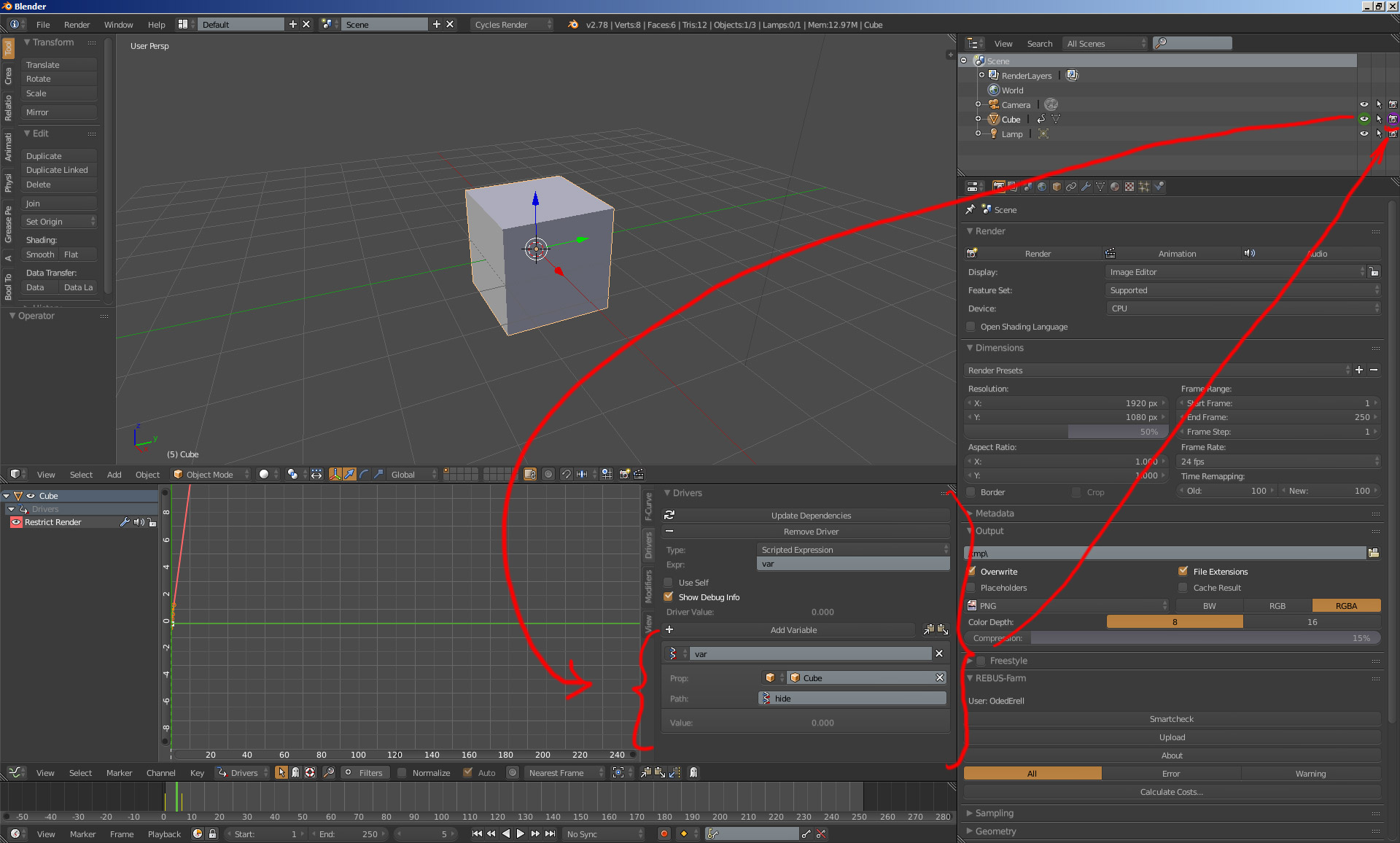
When setting key-frames to an object’s Visibility or “restrict view-port visibility” property,
Its easy to forget that it doesn’t affect the visibility in rendering but only in the view-port display.
This gave me some really nasty glitches in production when rendered animation turned out different than what I had expected.

Simple solution to that is:
Whenever an object’s visibility needs to be animated,
First thing to do is to set a Driver for the “restrict rendering” property, that would be controlled by the “restrict view-port visibility” property.
That way the animation done on view-port visibility will automatically also control rendering visibility.
What’s needed is a simple single property driver which is very simple to setup and the huge headaches can be avoided that way.

There are plenty of video tutorials about setting up drivers in Blender:
https://www.youtube.com/results?search_query=blender+2.7+drivers

Renderability_Controlled_by_Visibility