UE4 – Using a Post Process material to create a simple fog effect

Software:
Unreal Engine 4.24

An example of a simple fog effect created using a Post Process material:


The fog material Blueprint:
The method for creating the fog effect is to take distance of the objects from the camera, map it to a value range suitable for color blending 0 – 1, and use that for blending the object’s color with the fog color, so the further away the object, the more it will be colored by the fog.
Start by creating a new material, and follow the details below to create the Blueprint:

Fog_PP_material

  1. The Material Domain is set to Post Process.
    And has its Blendable Location parameter set to Before Tonemapping so it will be applied on the raw render.
    Annotation 2020-05-04 011312
  2. A SceneTexture node with its Scene Texture Id parameter set to PostProcessInput0 serves as the input of the view’s original rendered pixel colors:
    Annotation 2020-05-04 011050
  3. A Lerp (LinearInterpolate) node calculates the blending of the view’s original pixel colors with the Fog color to create the fog effect.
  4. A SceneTexture node with its Scene Texture Id parameter set to SceneDepth serves as the input of depth of each pixel (distance from camera):
    Annotation 2020-05-04 012256
  5. A ComponentMask node set to the R channel allows using the depth data as a single float value instead of a Vector4:
    Annotation 2020-05-04 012603
  6. A Clamp node is used to clamp (limit) the depth value to the Fog’s maximum depth value (see below)
  7. A RemapValueRange maps the distance value to a fog density value that will be used as the Lerp (3) alpha parameter.
    Simply put, the further the object, the more the original color will be blended with the fog color.
  8. A Power node (raises the fog blend factor by an exponent) make the fog blending non-linear, that is beginning gently for closer objects and than increasing more drastically as the distance grows (provided that the exponent value is above 1)
  9. A Constant Vector4 serves as an input for the fog color.
    * Note that having this input be a Vector4 and not a Vector3 allows it to be interpolated with the PostProcessInput0 data, otherwise a ComponentMask (RGB) node would have been necessary to convert the PostProcessInput0 to a Vector3.
  10. a float constant serves as an input for the fog’s minimal distance (from camera)
  11. a float constant serves as an input for the fog’s maximal distance (from camera)
    *  Note that it’s connected both to the Clamp node and to the RemapValueRange node.
  12. a float constant serves as an input for the fog’s minimal opacity (blend amount)
  13. a float constant serves as an input for the fog’s maximal opacity (blend amount)
  14. a float constant serves as an input for the fog’s blend exponent.


Applying the Post Process material to the level:

Fog_2

  1. Select the PostProcessVolume actor in the World Outliner window.
    * Create a PostProcessVolume actor if necessary.
  2. In the Details panel, under Rendering Features > Post Process materials,
    Add a new item to the array, in the new item’s value choose Asset Reference,
    And then select your fog material:
    Annotation 2020-05-04 015354
    Annotation 2020-05-04 015831


Related:

  1. Material Functions
  2. Blending materials
  3. Blending materials using texture paint

Arnold for 3ds max – Render objects as volumes (volume shading)

Software:
3ds max 2019 | Arnold 5

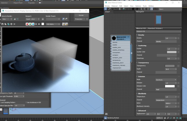
In-order for objects in 3ds max to be rendered as volumes with Arnold, the object mesh has to be converted to a volume, and a Standard Volume material assigned to the object:

  1. Add an Arnold Properties modifier to the object.
  2. Under Volume set the Step Size to a value higher than 0.0.
    Untitled-4
  3. Assign a Standard Volume material to the object and set it’s parameters to design the volumetric effect:
    Untitled-2

Examples:

* Note that both Density and Depth control the transparency or ‘thickness’ of the volume. (lower Depth setting creates a thicker volume)
* When Scattering is set to 0.0 the volume will have only a absorption effect

Untitled-1.jpg

Untitled-2.jpg

Untitled-3.jpg

In this example an Arnold Noise map is connected to the Standard Volume‘s Density parameter:
* Note that the Scale values must be set correctly in order to actually get a ‘cloudy’ effect.
* Note that the noise color values are now controlling the Density of the volume.

Untitled-1

Related:
Arnold for 3ds max God Rays


Arnold for 3ds max – Volumetric Fog and ‘God Rays’

Software:
3ds max 2019 | Arnold 5

a

Adding a ‘Volume Light’ effect in Arnold for 3ds max is fairly simple:

  1. In the Render Setup windows > Arnold Renderer tab, under Environment, Background & Atmosphere:
  2. Click the Scene Atmosphere material slot, add an Arnold Atmosphere Volume material to it,
    And drag it as an instance to the Material Editor to edit it’s parameters.
    Untitled-3
  3. Set the Density to a higher than 0.0 value, so the material will have an effect.
  4. You’ll probably need to significantly raise the number of samples in the Atmosphere Volume material, and also the number of Volume samples in the light settings in order to get a clean render.

Untitled-1.jpg

Related:
Arnold for 3ds max Volume Shading

3ds max Island / Seashore opacity underwater tip

Software:
3ds max 2016

When creating a surface submerged in sea water,
Theoretically, it’s the Volume Absorption or ‘Fog‘ of the water shader that should do cause the surface to disappear under water.
But in many cases that doesn’t work well because we don’t actually model enough extended surface under the water for it to completely disappear without seeing the surfaces geometric edges that spoil the result.

One of the oldest tricks in the book is to use a Gradient Ramp map in the surface’s Opacity channel to make it gradually disappear before the geometry ends.

This can be done in most  3d software and render engines, I’m demonstrating it here using 3ds max and V-Ray:

Island


UE4 – Connect a Directional Light to an Atmospheric Fog effect

Software:
Unreal Engine 4.21

UE4‘s Directional Light mimics sun lighting and shadow fairly realistically,
And the Atmospheric Fog visual effect produces a realistic clear sky background that includes the sun’s disk image in the sky.
> The Atmospheric Fog produces a result similar to an implementation of a Preetham physical sky model in common rendering software.

Combined together, these two elements can produce an effective day-light system,
But inorder for this to work the sun’s direction should be controlling the time of day simulated by the Atmospheric Fog.

For the Directional light to control the Atmospheric fog:
In the Directional Light’s details, under light, expend the settings and enable:
Atmosphere / Fog Sun Light

Note:
There is a limitation to this setup’s realism because the sunlight’s color shouldn’t be pure white, but rather yellowish, to orange, depending on the time of day (you can find tables of the sunlight’s color temperature for various time of day on the web)
There is no problem setting the sun’s color, but the problem is that it causes additional coloring of the Atmospheric Fog which isn’t needed since it already is simulating the sky’s color correctly.
The result of this limitation is that we can see a sunset sky with a white sunlight which is wrong.
I didn’t find a workaround for this yet, can’t find a way to set the Atmospheric Fog‘s sun vector without connecting it to a Directional light and can’t find a way to make the Directional Light‘s color not affect the Atmospheric Fog‘s color.

Update:
It seems this limitation can be overcome by disconnecting the Atmospheric Fog from the Directional Light and using the Atmospheric Fog Object’s rotation to control it.

Directional_light_Affect_Atmo_Fog
atmo_fog.gif

Related:

  1. UE4 HDRI Lighting
  2. 3ds max & V-Ray to UE4 Datasmith workflow
  3. Unreal – Architectural glass material
  4. Unreal – Camera animation

Cycles – Nested Refractive Volumes

Software:
Blender 2.79 | Cycles Renderer

When it comes to rendering nested refractive volumes, like a glass containing a beverage, the way to set it up in Cycles is common to many modern ray-tracers.
The touching bodies of refractive material like glass and liquid must overlap each other slightly so that rays being traced “meet” the right surface without having surfaces touching and causing “Z fighting” artifacts.

Transparencies_Air_Bubbles-01

When the render includes volumetric shading, like Volume Absorption (sometimes referred to as “fog”), the meshes must be set-up in a certain way for Cycles to interpret the volumes properly.

Intersecting volumes like a beverage glass and liquid must be separate objects to be rendered correctly. When joined into one mesh the renderer doesn’t treat the different volumes separately even though they have different shaders.
And the result is that the volume (depth) of the inner volume is calculated as just the depth on the intersection (the overlap) of the volumes.
In this example the wine can’t be rendered correctly when the glass and liquid meshes are joined.
The wine liquid doesn’t get it’s deep color because the renderer “thinks” it’s very thin.

Untitled-1.jpg

When the meshes are separated the renderer interprets the wines volume correctly and the Volume Absorption shader produces the right color:

Untitled-2

Setting up cavities within a volume like air bubbles, is similar to many other modern ray-tracers. You just have to create inner meshes that have flipped normals facing inwards, so air bubbles within the wine don’t need to have “air” material, they have the same wine shader, but have their faces flipped.

Note that in this case, it’s the other way around from the previous example.
If the bubble meshes are separate from the liquid mesh the renderer doesn’t interpret them as holes in the liquid volume, and produces an incorrect result:

Untitled-3

When the bubble meshes are joined to the liquid mesh, the volume is interpreted correctly:

Untitled-4.jpg

In short:
For these refractive volumetric effects to be rendered correctly in Cycles,
Surfaces of the same material volume must be joined to one mesh, and separated from meshes belonging to different material volumes.
* This may sound trivial, but it’s not. there are rendering systems in which only the surface shader determines volume interpretation and that has advantages like the convenience to aninate bubbles as separate objects from the liquid itself or the ability to join a glass bottle with the liquid into one mesh model.


Related:
> Understanding Transparency Render Settings

Arnold for Maya – Transmission Scattering (Ray Traced SSS)

Software:
Maya 2018 | Arnold 5

Scatter

The Arnold Standard Surface Shader’s Transmission Scattering options can be used for simulating highly realistic volumetrically ray-traced sub-surface-scattering suitable for materials like wax, soap, milk etc.

While the Transmission Depth attribute controls volumetric light absorption within the object (fog), the Scatter attribute controls what percentage of the light will be scattered instead of absorbed, effectively creating the murky effect of semi-transparent materials.

Note that for the scattering effect to work Scatter must have a dominant percentage value, and the Depth attribute must generally be much lower (shallower) than what would create coloring without scattering, otherwise the object will continue to look transparent and lacking the internal substance that we want to simulate.

Also note that the Opaque attribute must be unchecked in the Arnold attributes of the object’s shape node for the light to be able to pass into the mesh and illuminate the volume.
*This is actually a “cheat”, because physical semi-transparency has to be simulated by indirect light calculation or caustics, but for dense volumes like wax it’s very effective and the loss of realism is insignificant.

Untitled-1

Untitled-2.jpg

You can simulate the effect more accurately by rendering caustics,
In that case the Opaque attribute in the Arnold attributes of the object’s shape node must be checked and more steps must be taken allow refractive caustics to be ray-traced.

Note that simulating the effect using caustics will be very demanding in Transmission samples and Ray Depth.

Scatter_Caustics

Related:
>
Understanding Transparency Render Settings
>
Arnold Translucency
> Arnold Refractive Caustics