Understanding Transparency Render Settings

In theory, all clear* refractive surfaces should have their shadow calculated using a refractive caustics calculation in-order to render the refractive lensing** effect correctly, have their transparency color calculated as volumetric absorption of light through the medium in-order to render the color correctly for areas of different thickness, and have not only external reflections, but also internal reflections calculated, in-order to render the interaction between light and the transparent body correctly.
However, for thin surfaces of even thickness, like window glazing and car windshields, these optical effects can be rendered in much cheaper (non physical) methods, with very little compromise on final image quality or look, and even have an easier setup in most cases.
For this reason most popular render engines have object (mesh) and material (shader) parameters that allow configuration of the way these transparency effects will be rendered.
In this short article we’ll cover the different methods for rendering transparency effects, the reasoning behind them and the way to configure these settings in different render-engines.

In the comparison images below (rendered with Cycles), the images on the left were rendered with physically correct glass settings, 8192 samples + denoising,
And the images on the right were rendered with “flat” transparency settings and 1024 samples + denoising.
> See the shader settings below
Note that while for the monkey statue, the fast flat transparency settings produce an unrealistic result, the window glazing model loses very little of its look with the flat fast settings:

Transparency_Settings

Lensing, caustics and transparent shadows:

3D-Rendering-of-glassware

It’s a common intuitive mistake, that transparent objects don’t cast shadows, but they actually do. they don’t block light, they change its direction. light is refracted through them, gets focused in some areas of their surroundings (caustics) but can’t pass through them directly, so a shadow is created.
A good example of this would be a glass ball, acting like a lens, focusing the light into a tiny area, and otherwise having a regular elliptical shadow. if we tell the render-engine to just let direct light pass through the object we won’t get a correct realistic result, even if the light gets colored by the object’s transparency color.
There is however one case where letting the direct light simply pass through the object can both look correct and save a lot of calculations, and that is when the object is a thin surface with consistent thickness like window glazing.
So in many popular render-engines, when rendering an irregular thick solid transparent body like a glass statue or a glass filled with liquid, we have to counter-intuitively set the object or material to be opaque for direct light and let the indirect refracted light (caustics) create the correct lensing effect (focused light patterns in the shadow area)
> physically, light passing through a material medium is always refracted, i.e. indirect light. but for thin surfaces with even thickness like glazing, the lensing effect is insignificant, and can be completely disregarded by letting light pass directly through the object and be rendered as ‘transparent shadow’.
So the general rule regarding calculating caustics (lensing) vs casting transparent shadows (non physical), is that if the transparent object is a solid irregular shape with varying thickness like a statue or a bottle of liquid it should be rendered as opaque for direct light but with fully calculated caustics i.e. refracted indirect light.

Transparency color:

Cola_Test_ODED_ERELL_3D_Crop_signed

Physically, the color of transparency*** is always created by volumetric absorption of light traveling within the material medium. as light travels further through a material, more and more of it’s energy gets absorbed in the medium**** (converted to heat), therefore the thicker the object, less light will reach its other side, and it will appear darker. this volumetric absorption of light isn’t consistent for all wave lengths (colors) of light so the object appears to have a color.
For example, common glass, absorbs the red and blue light at a higher rate than green light, and therefore objects seen through it will appear greenish. when we look at the thin side of a common glazing surface we see a darker green color because we see light that has traveled through more glass (through a thicker volume of glass) because of refraction bending the light into the length of the surface. tea, in a glass, generally looks dark orange-brown, but if spilled on the floor it will ‘lose’ its color, and look clear like water because spilled on the floor, it’s too thin to absorb a significant amount of light and appear to have a color.
Most render engines allow setting the transparency (“refraction”/”transmission”) color of the material both as a ‘flat’ non physical filter color, and as a physical RGB light absorption rate (sometimes referred to as ‘fog’ color), that can in some cases be more accurately tuned by additional multiplier or depth parameters.
Setting an object’s transparency color using physical absorption (fog) usually requires more tweaking because in this method, the final rendered color is dependent not only on the color we set at the material/shader, but also on the model’s actual real world thickness.*****
In general, the transparency color of thick, solid, irregularly shaped objects (with varying thickness) must be set as a physical absorption rate color, and not as a simple filter color, otherwise the resulting color will not be affected by the material thickness, and look wrong.
For thin surfaces with consistent thickness, like window glazing, however, it’s more efficient to setup the transparency color as a ‘flat’ filter color, because it’s more convenient and predictable to setup, and produced a correct looking result.
For example, if we need to render an Architectural glazing surface that will filter exactly 50 percent of the light passing through it, it’s much simpler to set it up using a simple 50% grey transparency filter color, because this method disregards the glass model’s thickness. This approach isn’t physical, but for an evenly thick glazing surface, the result has no apparent difference from a physical volumetric absorption approach to the same task.

Internal reflections:

Diamond-close-up-inspection

It’s not intuitive to think that the air surface itself has reflections when seen through a transparent material volume like water or glass.
Viewed from under water, the air surface above, acts like a mirror for certain angles, reflecting objects that are under water. a glass ball lit by a lamp has a very distinct highlight, which is the reflected image of the light source itself (specular reflection), but it also has an internal highlight appearing on inside where the glass volume meets the air volume. we can easily ‘miss’ this internal highlight because in many cases it’s appearance converges with the bright focused light behind the ball, caused lensing (refractive caustics). the distinctly shiny appearance of diamonds, for example, is very much dependent on bright internal reflections, diamond cutting patterns are specifically designed to reflect a large percentage of light back to the viewer and look shiny, and if we wish to create a realistic rendering of diamonds, we will not only have to setup the correct refractive index for the material, but also model the geometric shape of the diamond correctly, and of course, set the material to render both external (“regular”******) reflections and internal reflections.
Your probably already guessing what I’m about to say next..
For thin surfaces with even thickness, the internal reflection is barely noticeable, because it converges with the main surface reflection, an for this reason, when rendering window glazing, car windshields, and the like, we can usually turn the internal reflections calculation off to save render time.

Underwater_31.12.18

Render Settings:

Simplified settings summary table:

Flat (Glazing) Physical (irregular volume)
Shadow Transparent Caustics
Color Filter Volumetric Absorption
Reflections External only External and Internal

Example Cycles (Blender) shaders:
> The Flat glazing shader is actually more complex to define since it involves defining different types of calculations per different type of rays being traced (cheating).
In general, for Shadow and Diffuse rays that shader is calculated as a simple Transparent shader and nor a refraction shader, and when back-facing, the shader is calculated as pure white transparent instead of glossy to remove the internal reflections.
> While the flat glazing shader is only connected to the Surface input of the material output, the physical glass shader has also a Volume Absorption BSDf node connected to the Volume input of the material output node.
> Note that a simple Principled BSDF material will have flat transparency and physical shadow (caustics) by default.
> For caustics to be calculated, the Refractive Caustics option has to be enabled in the Light Path > Caustics settings in the Cycles render settings.

Cycles

Example V-Ray Next for 3ds max material settings:
>
In V-Ray for 3ds max (and Maya) the Affect Shadows parameter in the VrayMtl Refraction settings determines weather the shadows will be fake transparent shadows suitable for glazing or (on) or opaque (off) which is the suitable setting for caustics.
> The caustics calculation is either GI Caustics which is activated by default in the main GI settings or a dedicated Caustics calculation that can be activated, also in the GI settings.
> For flat glazing the color is defined as Refraction Color and for physical glass the Refraction color is pure white and the glass color is set as Fog color.

V-Ray_Glass

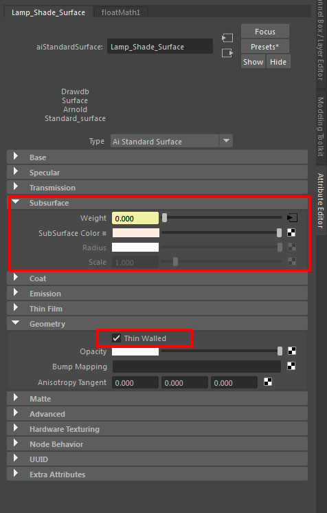
Example Arnold for Maya settings:
> In Arnold 5 for Maya the Opaque setting in the shape node Arnold attributes must be unchecked for transparent shadows, and checked for opaque shadows suitable for caustics.
> For rendering refractive caustics in Arnold for Maya more settings are needed.
> When the Transmission Depth attribute is set to 0 the Transmission Color will be rendered as flat filter color, and when the Transmission Depth attribute is a value higher than 0 the transparency color will be calculated as volumetric absorption reaching the Transmission Color at the specified depth.

ArnoldMaya

General notes:

> in Brute Force Path Tracers like Cycles and Arnold the Caustics calculation is actually a Diffuse indirect light path. this seems un-intuitive, but the light pattern appearing on a table surface in the shadow of a transparent glass is actually part of the table surface’s diffuse reflection phenomenon.

> what we refer to as ‘Diffuse Color’ in dielectric (non-metals) is actually a simplification of absorption of light scattered inside the object volume (SSS).

* Optically all dielectric materials (non-metals) are refractive, but not all of them are also clear, the is, most of them actually have micro particles or structures within their volume, that scatter and absorb light that travels through them, creating the effects we’re used to refer to as “Subsurface Scattering” (SSS) and in the higher densities “Diffuse reflection”.

** Lensing is a term used to describe the effect of a material medium bending light, focusing and dispersing it, and so acting as a lens.

*** Actually all color in dielectric (non metallic) materials is created by Volumetric Absorption.

**** Light isn’t only absorbed as it travels through medium, it’s also scattered.

***** Volumetric shading effects usually use the model original scale (the true mesh scale), so to avoid unexpected results it’s best that the object’s transform scale will be 1.0 (or 100% depending on program annotation)

Related Posts:
>
Cycles Nested Transparencies
>
Arnold for Maya Refractive Caustics
> Arnold for Maya Transmission Scattering
> Understanding Fresnel Reflections
> Advanced Architectural Glazing shader for Blender
> V-Ray Underwater Rendering

Arnold for 3ds max – Render objects as volumes (volume shading)

Software:
3ds max 2019 | Arnold 5

In-order for objects in 3ds max to be rendered as volumes with Arnold, the object mesh has to be converted to a volume, and a Standard Volume material assigned to the object:

  1. Add an Arnold Properties modifier to the object.
  2. Under Volume set the Step Size to a value higher than 0.0.
    Untitled-4
  3. Assign a Standard Volume material to the object and set it’s parameters to design the volumetric effect:
    Untitled-2

Examples:

* Note that both Density and Depth control the transparency or ‘thickness’ of the volume. (lower Depth setting creates a thicker volume)
* When Scattering is set to 0.0 the volume will have only a absorption effect

Untitled-1.jpg

Untitled-2.jpg

Untitled-3.jpg

In this example an Arnold Noise map is connected to the Standard Volume‘s Density parameter:
* Note that the Scale values must be set correctly in order to actually get a ‘cloudy’ effect.
* Note that the noise color values are now controlling the Density of the volume.

Untitled-1

Related:
Arnold for 3ds max God Rays


Arnold for 3ds max – Volumetric Fog and ‘God Rays’

Software:
3ds max 2019 | Arnold 5

a

Adding a ‘Volume Light’ effect in Arnold for 3ds max is fairly simple:

  1. In the Render Setup windows > Arnold Renderer tab, under Environment, Background & Atmosphere:
  2. Click the Scene Atmosphere material slot, add an Arnold Atmosphere Volume material to it,
    And drag it as an instance to the Material Editor to edit it’s parameters.
    Untitled-3
  3. Set the Density to a higher than 0.0 value, so the material will have an effect.
  4. You’ll probably need to significantly raise the number of samples in the Atmosphere Volume material, and also the number of Volume samples in the light settings in order to get a clean render.

Untitled-1.jpg

Related:
Arnold for 3ds max Volume Shading

Basic Cloth Material in Arnold for Maya

Software:
Maya 2018 | Arnold 5

An example of a basic traditional (not scanned) cloth material setup in Arnold 5 for Maya using an aiStandardSurface shader.

Untitled-1.jpg

The shading network uses a classic angle dependent color blend to simulate the color of the cloth being washed out at grazing angle of view.

Explanation of the node graph:

Untitled-2.jpg

  1. A black and white fabric weave texture that will serve as input for multiple shading channels.
    * This is actually not the best example of such a pattern, and could be replaced with a much better texture.
    cotton grey bump
  2. A remapValue node is used to set contrast to the fabric pattern (reduce contrast in this case) prior to it being multiplied with the fabric colors.
    * Note that only one of the textures RGB channels is connected to the remapValue node since it’s a float (mono) processor and not RGB.
    Untitled-3
    * Note that depending on the fabric texture, you may have to design different curves to achieve the right effect.
  3. Two colors are defined with colorConstant nodes:
    A deep color as the main fabric color, and a washed out color for grazing angle view (“side color”).
  4. An aiFacingRatio node is used as an input for incident angle info.
    * Note that in this case I checked the node’s invert option to make it behave more like other systems I’m used to (if you don’t use invert, the angle blend curve in 5 will be different..)
  5.  A remapValue node used to set the angle blend curve or in other words, how much does the color appears washed out per change of view angle of the cloth surface.
    * The longer it take the curve to become steep from left to right, the more the main color will be dominant before the washed out color will appear.
    Untitled-4
  6. A colorCorrect node is used in this example just as a way to convert the remapped float value back to RGB for being multiplied with the cloth colors.
    * We could also connect it directly to the individual float components of the RGB colors but this way the node graph is cleaner.
  7. A multiplyDivide node is used to multiply the processed fabric texture with the 2 fabric colors “baking” the pattern into the color.
  8. A blendColors node is used to blend the 2 processed fabric colors together according to the processed facingRatio angle input.
    The result is the final cloth color that is connected to the aiStandardSurface shader.
  9. An aiBump2d node is used to convert the fabric pattern to normal data that will be connected to the aiStandardSurface shader to produce bumps.
  10. An aiStandartSurface shader serving as the main shading node for this material.
    * Note that under Geometry the Thin Walled option is checked so that the Subsurface layer of the shader will act as a Paper Shader rather than SSS.
    * The main cloth color is connected to the SubSurface Color input.
    Untitled-5


More Arnold shading posts

Arnold for Maya – Transmission Scattering (Ray Traced SSS)

Software:
Maya 2018 | Arnold 5

Scatter

The Arnold Standard Surface Shader’s Transmission Scattering options can be used for simulating highly realistic volumetrically ray-traced sub-surface-scattering suitable for materials like wax, soap, milk etc.

While the Transmission Depth attribute controls volumetric light absorption within the object (fog), the Scatter attribute controls what percentage of the light will be scattered instead of absorbed, effectively creating the murky effect of semi-transparent materials.

Note that for the scattering effect to work Scatter must have a dominant percentage value, and the Depth attribute must generally be much lower (shallower) than what would create coloring without scattering, otherwise the object will continue to look transparent and lacking the internal substance that we want to simulate.

Also note that the Opaque attribute must be unchecked in the Arnold attributes of the object’s shape node for the light to be able to pass into the mesh and illuminate the volume.
*This is actually a “cheat”, because physical semi-transparency has to be simulated by indirect light calculation or caustics, but for dense volumes like wax it’s very effective and the loss of realism is insignificant.

Untitled-1

Untitled-2.jpg

You can simulate the effect more accurately by rendering caustics,
In that case the Opaque attribute in the Arnold attributes of the object’s shape node must be checked and more steps must be taken allow refractive caustics to be ray-traced.

Note that simulating the effect using caustics will be very demanding in Transmission samples and Ray Depth.

Scatter_Caustics

Related:
>
Understanding Transparency Render Settings
>
Arnold Translucency
> Arnold Refractive Caustics

Using Arnold’s Ambient Occlusion node to create an eroding paint shader effect

Software:
Maya 2018 | Arnold 5

Arnold’s Ambient Occlusion (dirt) node can be used as a procedural mask to create interesting material effects like in this example of paint that is eroded at the model’s bulging areas to reveal metal beneath it.

In this shader’s case the Ambient Occlusion node is connected to the Mix property of an Arnold Mix shader, that blends between two different Arnold Standard Surface shaders, one simulating the underlying tin metal, and the other simulating the red paint that covers it.

Note that in the Ambient Occlusion node the Invert Normals property is checked, so that the effect will create a mask for the bulges and not for the creases,
And also that the Self Only property is checked so that the node will behave as a fixed object mask disregarding the proximity of other objects.
In this example the output of the Ambient Occlusion node is also process using a Remap Value node to increase it’s contrast so it will define borders between the areas.

Paint-Metal.jpeg

Untitled-1.jpg

Untitled-1

Arnold for Maya Depth of Field (DOF)

Software:
Maya 2018 | Arnold 5

Untitled-2.jpg

  1. In the camera shape node’s Arnold Attributes:
    Check ‘Enable DOF’.
  2. Set ‘Aperture Size’ and ‘Focus Distance’ to control the effect.
    Note:
    The Aperture Size attribute isn’t an f-number aperture like we would expect in photography but a radius in world units.
    Larger Aperture Size values (larger lens Iris opening), and shorter Focus Distances will cause a narrower Depth of Field which will result in the background appearing more blurry.
    DOF is generally more apparent with ‘long lenses’ (shorter focal length).
  3. Set other Aperture attributes like the number of blades and aspect ration to further design the appearance of out of focus areas and especially highlights.
    * The optical effect referred by the term ‘Bokeh’ in photography.


Related Posts:

Arnold for Maya Motion-Blur

After Effects Camera Lens Blur

Arnold for Maya Standard Surface Shader Translucency / Paper Shader

Software:
Maya 2018 | Arnold 5

Translucent
In this example, the lamp shade has a Translucent material

The Subsurface component of the Arnold Standard Surface shader (aiStandardSurface) controls Sub Surface Scattering (SSS).
When the ‘Thin Walled’ option is checked in the Geometry attributes of the shader, the Subsurface isn’t rendered as a full volume of material like soap or skin/flesh (the effect that is traditionally called Subsurface Scattering – SSS) but as a thin paper-like translucent surface like paper, thin cloth thin leaves, lamp shades etc. (the effect traditionally called Translucency or ‘Paper Shader’)

* Note that this option is suitable mainly for polygon surfaces without thickness (just one side)

Untitled-1

To create a Translucent shader with Arnold:

Subsurface Weight must be higher than 0.0 for the effect to be computed.

In Geometry, check Thin Walled for the SSS to be rendered as Translucency (Paper Shader).

Extra options:

Use samplerInfo Node Facing Ratio output in Subsurface weight to add realism by changing the weight by angle.

Multiply weave texture with Facing Ratio to simulate fabric translucency.

Untitled-3.jpg

Related:
> Understanding Transparency Render Settings
> Arnold Transmission Scattering
> Arnold Refractive Caustics

Arnold renderer – First impressions

Software:
Maya 2018 | Arnold 5

As a 3D rendering instructor I’ve been recently required to get familiar with rendering animations using Arnold for Maya so that I’ll be able to train VFX / Animation students to do so.

So today, after about 15 years since the last time I worked with Maya, I installed the latest version of the software’s educational edition on my PC, and started finding my way around the basics, and rendering with the Arnold renderer.

So obviously, the Arnold renderer is a state of the art production ray-tracer for the film VFX industry, and it sure feels that way with its no-nonsense super-realistic uncompromising physical approach to all the aspects of rendering, giving the artist total freedom to configure whatever he or she can possibly want,
And for someone with an understanding of physical definitions of light sources, optical attributes of surfaces, physical shaders and the technical process of ray-tracing, it’s an absolute joy to use.

So what’s the problem?

The problem is that the Arnold renderer wasn’t developed as a practical rendering solution for independent artists relaying on one or two PC CPU’s as the main rendering work force.
Arnold’s Brute Force rendering approach is very convenient to use and provides awesome shading quality, but it requires massive processing power to be practical in production of animations, even with today’s multicore desktop CPU revolution that was started with AMD launching the Ryzen chips.

* I must admit that (in the field of 3D visualization) I got spoiled by using Mental Ray and V-Ray over the years and got used to rendering with at least 3 bounces of indirect diffuse illumination,
Something that using interpolated GI calculations like irradiance caching and such can be done relatively fast on a desktop PC, but using accurate Brute Force to do it (on a desktop PC CPU) makes it impractically too slow.

The good news:

A) The GPU rendering revolution that was enabled by the nVidia Cuda technology is making massively parallel Brute Force rendering practical at a fraction of the price of CPU processing power.
Example:
About 3 years ago I decided I must check what’s this “Cuda rendering” all about, so I purchased a Geforce Gtx Titan Black GPU (Geforce 7 series) for about 1200$.
That GPU had Brute Force rendering power equivalent to about 16 3Ghz CPU cores.
Today you can get the same speed and memory with a 300$ Geforce Gtx 1060 GPU.
But Arnold isn’t a GPU renderer.. one may rightfully say….
* It should be said that GPU rendering is currently limited in the amount of memory compared to CPU rendering, and also OSL shaders are not supported.

B) Cycles renderer, Blender’s own built-in render engine is a GPU renderer, and it’s very similar to Arnold in its highly physical no-nonsense Brute Force rendering approach.
So if you wish to enjoy an “Arnold Style” physical shading and Brute Force rendering workflow in a small indie studio environment, GPU rendering with Blender and Cycles is a good way to do that, plus the software is free.
A relatively modest investment in 2 Geforce Gtx 1070 GPUs will give you Brute force rendering power roughly equivalent to 40 3Ghz CPU cores, at about a 4th or a 5th of the price it would cost in CPU’s.

All that being said..
Arnold is absolutely awesome! 😀

Update:
It seam that a version of Arnold that can render on GPU is on it’s way, and this is great news!