UE4 – HLSL texture sample quick tip

Software:
Unreal Engine 4.26

When sampling textures using an HLSL custom node,
The UE4 TextureObject input name, will automatically have a sampler object generated named:

<your TextureObject name>sampler

For example, if you named your TextureObject input “tex_in”, the available sampler will be named “tex_insampler”.
So the code for sampling the texture will be:

Texture2DSample(tex_in, tex_inSampler, coords);

The following is an example of a simple u-blur custom node code, with 4 node inputs:
1. tex_in – TextureObject
2. coords – float2
3. size – float
4. sample – float

int blur_samples = int(samples * 0.5f);
float3 col = 0.0f;
float2 sample_coords = 0.0f;
for (int i = -blur_samples; i < blur_samples; i ++)
{	
	sample_coords.x = i * (size / blur_samples * 2);
	col += Texture2DSample(tex_in, tex_inSampler, coords + sample_coords ) / (blur_samples * 2);
}
return col;

The above code can typed directly in the Custom node’s Code field. or loaded from an external .usf file.

See also:
Loading HLSL shaders from the project folder

UE4 – Loading shaders from within the project folder

Software:
Unreal Engine 4.25

*Also tested on Unreal Engine 5.0.1

Disclaimer:
I’m probably the 10th guy that’s documenting these steps on the web,
I didn’t come up with this solution myself, I learned it from the sources listed below.
The reason I’m documenting this (again) myself is to have a clear source I can come back to for this issue because I’m absolutely incapable of remembering subjects like this…… :-\
If you find inaccuracies in the steps I’m detailing or my explanation, I’ll be very grateful if you share a comment.

  1. https://forums.unrealengine.com/development-discussion/rendering/1562454-virtual-shader-source-path-link-custom-shaders-shadertoy-demo-download
  2. https://dinwy.github.io/study/2019/july/customShaderInUE4/
  3. https://forums.unrealengine.com/community/community-content-tools-and-tutorials/1710373-using-external-shader-files-ush-usf-and-getting-the-most-of-the-custom-node

In short:
AFAIK since version 4.21 UE doesn’t load custom node shader code from your project/Shaders folder by default anymore, but only from the shaders folder in the engine installation, which makes it less practical for developing shaders for specific projects.


Steps for setting the UE project to load shaders from the project folder in UE 4.22:

> The examples here are for a project named: “Tech_Lab”

A. The project must be a C++ project:

So either create a new project, define as such or just create a new C++ class and compile the project with it to convert it to a C++ project.
Notes:
a. You may need to right click the .uproject file icon and and Generate Visual Studio Project Files for the project to load correctly into Visual Studio and compile.
b. You can delete the unneeded C++ class you added after the new settings took place.

B. Create a folder for the shader files:

Typically, it will be called “Shaders” and will be placed in the project root folder.

C. Add the RenderCore module to the project:

This is done by adding string “RenderCore” to array of public dependency modules in the <project>.build.cs file:

PublicDependencyModuleNames.AddRange(new string[] { "RenderCore", "Core", "CoreUObject", "Engine", "InputCore" });
(see image)

Notes:
a. In UE 4.21 it should be ShaderCore.
b. This addition is needed in-order to compile a new primary project module (next step).

D. Define a custom primary module for your project:

In <project_name>.h file add a new module named F<project_name>Module, with a StartupModule function overrides.
Notes:
a. We have add an include statement for “Modules/ModuleManager”.
b. The <project_name>.h file is located in the /Source/<project_name> folder.
c. Some sources state that you also have to override the ShutdownModule function, with an empty override, it works for me without this (maybe its just a mistake..)

E. Implement the function override,
and set the custom module as the project primary module:

In <project_name>.cpp file, add the StartupModule override,
With the definition of the added shaders path:
FString ShaderDirectory = FPaths::Combine(FPaths::ProjectDir(), TEXT("Shaders"));

and mapping this new path as “/Project” for conveniently including it:
AddShaderSourceDirectoryMapping("/Project", ShaderDirectory);

Last thing to do is to replace “FDefaultGameModuleImpl” with our custom module name in the IMPLEMENT_PRIMARY_GAME_MODULE macro:
IMPLEMENT_PRIMARY_GAME_MODULE(FTech_LabModule, Tech_Lab, "Tech_Lab" );

Notes:
a. We must include “Misc/Paths”
b. Note that the addition of this folder mapping is restricted to versions 4.22 and higher via a compiler directive condition. for version 4.21, you should state “ENGINE_MINOR_VERSION >= 21:

Note for UE5:
Unreal Engine 5 supports this from the get go so this compiler directive condition should be deleted for this to work.

F. Wrapping up:

After taking these steps and compiling the project.
You should be able to include .ush and .usf files stored in <your_ue_project>/Shaders with the “Project” path mapping:
include "/Project/test.usf"

That’s it! 🙂

I hope you found this helpful,
And if you encountered errors, or inaccuracies,
I’ll be grateful if you’ll take the time to comment.


Related:

  1. UE4 – Cyber enhancement shader
  2. UE4 – Fog post process effect

UE4 – Triplanar projection mapping setup

Software:
Unreal Engine 4.25

Triplanar Projection Mapping can be an effective texture mapping solution for cases where the model doesn’t have naturally flowing continuous UV coordinates, or there is a need to have the texture projected independently of UV channels, with minimally visible stretching and other mapping artifacts.
Classic use cases for Triplanar Projection Mapping are terrains and organic materials. provided that the image being used is a seamless texture, no seams will be visible because this projection type isn’t affected by UV coordinates.
Triplanar Projection Mapping can also be used in world space to create a continuous texture between separate meshes, allowing the meshes to be indestructibly transformed and edited.

How does Triplanar Projection Mapping work?
Triplanar Projection Mapping is a linear blend between 3 orthogonal 2D planar texture projections, typically each aligned to a natural world or object axis.
The more the surface faces an axis, the higher the weight of this axis projection in the final blend.

UE4 local (object) space Triplanar Projection Mapping material setup:
* It’s usually more efficient to create this setup as a Material Function

  1. Local shading coordinates are multiplied by by a “density” parameter to allow convenient scaling of the projected.
  2. The scaled coordinates vector is separated to its components who are combined to 3 pairs of planar coordinates XY, XZ and YZ, and fed as the sample coordinates to the 3 Texture Sample nodes.
  3. The Vertex Normal input vector is transformed to local space, converted to absolute value (absolute orientation in the positive axes octant) and separated to its X, Y and Z components so they can serve as blend weights in the mix.
  4. Each of the 3 planar axis projections is multiplied by the blend factors, and the resulting values are added to the raw mix.
  5. A value of 1.0 is divided by the Normal vector component values to obtain the factor needed to normalize the blend result to a value of 1.0.
  6. The raw blend value is multiplied by the normalizing factor so the blend resulting color will be normalized.
    * The blend weights should add to a value of 1.0, but a unit vector’s values add up to more than 1 in diagonal directions. for this reason, without this final step, the color of the texture in point on the surface that are diagonal to the projection axes will appear brighter than in points on the surface that face a projection axis.

An example of Triplanar Projection Mapping in world space:

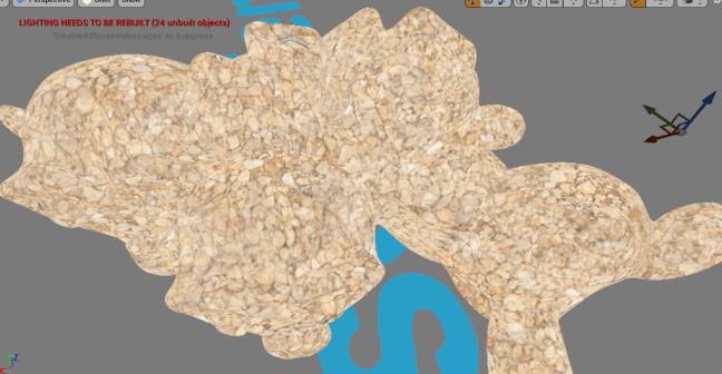
A bunch of Blender monkeys (Suzanne) continuously textured using world space Triplanar Projection Mapping:

Related posts:
UE4 – Material Functions
UE4 – Material Instances
UE4 – Bump mapping
UE4 – Procedural bump mapping

UE4 – Procedural 3D noise bump setups

Software:
Unreal Engine 4.25

Yet another case where I develop my own costly solution only to find out afterwards that there’s actually a much more efficient built-in solution.. 😀

In this case the subject is deriving a bump normal from a procedural or non-uv projected height map/texture (like noise, or tri-planar mapping for example).

The built-in way:
Using the pre-made material functions, PreparePerturbNormalHQ and PerturbNormalHQ, the first of which uses the low level Direct3D functions DDX and DDY to derive the two extra surface adjacent values needed to derive a bump normal, and the last uses the 3 values to generate a world-space bump normal:

240 instructions
  1. Noise coordinates are obtained by multiplying the surface shading point local position by a value to set the pattern density.
  2. The Noise output value is multiplied by a factor to set the resulting bump intensity.
  3. The PreparePerturbNormalHQ function is used to derive the 2 extra values needed to derive a bump normal.
  4. The PerturbNormalHQ function is used to derive the World-Space bump normal.
  5. Note:
    Using this method, the material’s normal input must be set to world-space by unchecking Tangent Space Normal in the material properties.

The method I’m using:
This method is significantly more expensive in the number of shader instructions, but in my opinion, generates a better quality bump.
Sampling 3 Noise nodes at 3 adjacent locations in tangent-space to derive the 3 input values necessary for the NormalFromFunction material function:

412 instructions
  1. Noise coordinates are obtained by multiplying the surface shading point local position by a value to set the pattern density.
  2. Crossing the vertex normal with the vertex tangent vectors to derive the bitangent (sometimes called “binormal”).
  3. Multiplying the vertex-tangent and bitangent vectors by a bump-offset* factor to create the increment steps to the additional sampled Noise values.
    * This factor should be parameter for easy tuning, since it determines the distance between the height samples in tangent space.
  4. The increment vectors are added to the local-position to get the final height samples positions.
  5. The NormalFromFunction material function is used to derive a tangent-space normal from the 3 supplied height samples.

Note:
From my experience, even though the UV1, UV2 and UV3 inputs of the NormalFromFunction are annotated as V3, the function will only work is the inputs are a scalar value and not a vector/color.

Related:
UE4 – Material Functions
UE4 – Bump map
UE4 – fix an inverted normal map
UE4 – Triplanar mapping

UE4 – Quick fix for normal map encoding

Software:
Unreal Engine 4.25 | Photoshop 2020

Quick UE normal map tip:
If you load a normal map into a UE material and the result appears inverted, i.e. holes instead of bumps or the other way:

The quick fix:

  1. In the texture settings, check the Flip Green Channel option and save it:

Annotation 2020-09-06 160838

The deep fix:
* This can be performed an automated action on multiple files

  1. Open the normal map in Photoshop
  2. In the Channels panel, select the Green channel
  3. Press Ctrl + I,
    Or Select Image > Adjustments > Invert
    To invert the green channel.
  4. Save the texture and reload into Unreal Engine.
    Annotation 2020-07-06 233156

Inverted normal map:Annotation 2020-07-06 232554

Fixed normal map:Annotation 2020-07-06 233036

Related:
UE4 Bump map
UE4 – Procedural Bump Normals

UE4 – Technical model visualization tips

Software:
Unreal Engine 4.25

This post is a summary of the tips given by Epic Games technical-artist Min Oh in his GDC 2017 lecture about improving photo-realism in product visualization, more specifically, how to render high quality surfaces.
I recommend watching the full lecture:

  1. Render sharper reflections by increasing the Cubemap resolution of reflection captures:
    Project Settings > Engine > Rendering > Reflection > Reflection Capture Resolution
    * use powers of 2 values i.e. 256, 512, 1024….
    Annotation 2020-07-06 195120
  2. Improve the accuracy of environment lighting by increasing the Cubemap resolution of the Skylight:
    * use powers of 2 values i.e. 256, 512, 1024….
    Annotation 2020-07-06 202415
  3. Improve screen space effects accuracy like screen space reflections by setting the engine to compute high precision normals for the GBuffer:
    Set Project Settings > Engine > Rendering > Optimizations > GBuffer Format to:
    High Precision Normals
    Annotation 2020-07-06 204022
  4. Use a high degree of tessellation (subdivision) for the models pre-import.
    Simpy put:
    Use high quality models.
  5. Improve the surfaces tangent space accuracy, and as a result also the shading/reflection accuracy by setting the model’s static mesh components to encode high precision tangent basis:
    Static Mesh Editor > Details > LOD 0 > Build Settings > Use High Precision Tangent basis
    Annotation 2020-07-06 210030
  6. Creating materials with rich dual specular layers by enabling material clear coat separate normal input:
    Project Settings > Engine > Rendering > Materials > Clear Coat Enable Second Normal
    Annotation 2020-07-06 211152Set the material Shading Model to Clear Coat and use a ClearCoatBottomNormal input node to add a normal map for the underlying layer:
    Annotation 2020-07-06 221027


Related:

  1. UE4 – Lighting calculation tips
  2. UE4 HDRI lighting
  3. UE4 – Enable DXR ray-traced reflections 

UE4 – Creating two sided material effects using the TwoSidedSign node

Software:
Unreal Engine 4.24

The TeoSidedSign node let’s the shader “know” if a rendered polygon is facing the camera or not by outputting a value of 1 for facing polys and -1 for back-facing polys.
This is useful for creating materials that have different properties when seen front-facing or back-facing.

Example 1:
Blending two different colors based on face direction:

  1. Check the Two Sided material attribute.
    * Needed so that the engine will render the polygons beck sides.
  2. In the material blueprint, create a blend of to colors using a Lerp (LinearInterpolate) node and connect it to the material’s Base Color input.
  3. Add a TwoSidedSign node to get polygon facing input (1,-1).
  4. Connect the TwoSidedSign node’s output to a Clamp node to clamp the values to (1,0).
  5. Connect the  Clamp node’s output to the Lerp node’s Alpha input so that the polygon’s facing direction will control the Lerp blend.

Note:
You can use this method to blend any other material attribute based on polygon facing direction.

Annotation 2020-05-11 133226


Example 2:
Create an “inwards facing” flipped normal material:

  1. Set the material’s Blend Mode to Masked.
    * Needed for being able to make areas parts of the mesh invisible.
  2. Check the Two Sided material attribute.
    * Needed so that the engine will render the polygons beck sides.
  3. Add a TwoSidedSign node to get polygon facing input (1,-1).
  4. Connect the TwoSidedSign node’s output to a Clamp node to clamp the values to (1,0).
  5. Connect the Clamp node’s output to a 1-X node to invert the facing input.
  6. Connect the 1-X node’s output to the material’s Opacity Mask input so that polygons facing the camera will be invisible.

Annotation 2020-05-11 130703


Related:

  1. Blending material using Paint
  2. Material Functions
  3. UE4 Bump Map

UE4 – Using a Post Process material to create a simple fog effect

Software:
Unreal Engine 4.24

An example of a simple fog effect created using a Post Process material:


The fog material Blueprint:
The method for creating the fog effect is to take distance of the objects from the camera, map it to a value range suitable for color blending 0 – 1, and use that for blending the object’s color with the fog color, so the further away the object, the more it will be colored by the fog.
Start by creating a new material, and follow the details below to create the Blueprint:

Fog_PP_material

  1. The Material Domain is set to Post Process.
    And has its Blendable Location parameter set to Before Tonemapping so it will be applied on the raw render.
    Annotation 2020-05-04 011312
  2. A SceneTexture node with its Scene Texture Id parameter set to PostProcessInput0 serves as the input of the view’s original rendered pixel colors:
    Annotation 2020-05-04 011050
  3. A Lerp (LinearInterpolate) node calculates the blending of the view’s original pixel colors with the Fog color to create the fog effect.
  4. A SceneTexture node with its Scene Texture Id parameter set to SceneDepth serves as the input of depth of each pixel (distance from camera):
    Annotation 2020-05-04 012256
  5. A ComponentMask node set to the R channel allows using the depth data as a single float value instead of a Vector4:
    Annotation 2020-05-04 012603
  6. A Clamp node is used to clamp (limit) the depth value to the Fog’s maximum depth value (see below)
  7. A RemapValueRange maps the distance value to a fog density value that will be used as the Lerp (3) alpha parameter.
    Simply put, the further the object, the more the original color will be blended with the fog color.
  8. A Power node (raises the fog blend factor by an exponent) make the fog blending non-linear, that is beginning gently for closer objects and than increasing more drastically as the distance grows (provided that the exponent value is above 1)
  9. A Constant Vector4 serves as an input for the fog color.
    * Note that having this input be a Vector4 and not a Vector3 allows it to be interpolated with the PostProcessInput0 data, otherwise a ComponentMask (RGB) node would have been necessary to convert the PostProcessInput0 to a Vector3.
  10. a float constant serves as an input for the fog’s minimal distance (from camera)
  11. a float constant serves as an input for the fog’s maximal distance (from camera)
    *  Note that it’s connected both to the Clamp node and to the RemapValueRange node.
  12. a float constant serves as an input for the fog’s minimal opacity (blend amount)
  13. a float constant serves as an input for the fog’s maximal opacity (blend amount)
  14. a float constant serves as an input for the fog’s blend exponent.


Applying the Post Process material to the level:

Fog_2

  1. Select the PostProcessVolume actor in the World Outliner window.
    * Create a PostProcessVolume actor if necessary.
  2. In the Details panel, under Rendering Features > Post Process materials,
    Add a new item to the array, in the new item’s value choose Asset Reference,
    And then select your fog material:
    Annotation 2020-05-04 015354
    Annotation 2020-05-04 015831


Related:

  1. Material Functions
  2. Blending materials
  3. Blending materials using texture paint

UE4 Material Blueprint Shortcuts

Software:
Unreal\n Engine 4.24

Some useful Unreal Editor Material Blueprint shortcuts:

  1. Hold 1 and LMB Click to create a 1D Constant node:
    Annotation 2019-12-26 005530
  2. Hold 2 and LMB Click to create a 2D Constant node:
    Annotation 2019-12-26 005549
  3. Hold 3 and LMB Click to create a 3D Constant node:
    Annotation 2019-12-26 005605
  4. Hold S and LMB Click to create a Scalar Parameter node:
    Annotation 2019-12-26 005618
  5. Hold V and LMB Click to create a Vector Parameter node:
    Annotation 2019-12-26 005631
  6. Hold L and LMB Click to create a Lerp (Linear Interpolate) node:Annotation 2019-12-26 005653
  7. Hold M and LMB Click to create a Multiply node:
    Annotation 2019-12-26 005722
  8. Hold A and LMB Click to create a Add node:
    Annotation 2019-12-26 005736
  9. Hold T and LMB Click to create a Texture Sample node:Annotation 2019-12-26 010504
  10. Hold U and LMB Click to create a Texture Coordinate node:
    Annotation 2019-12-26 010449
  11. Just press C to create a comment:
    Annotation 2019-12-26 005808

More UE4 Material Editing posts

UE4 – Basic Material Blending

Software:
Unreal Engine 4.24

The example explained in this article is creating a blend between a mud material, and a mud-leaves material using a mask (Alpha) texture.
>>
The scanned PBR materials in demonstrated in this post are from Texture Haven (texturehaven.com)

How does it work?
There is actually no blending of Unreal materials, but rather a regular Unreal material in which each of the parameters is defined as a linear blend between 2 different source values for that parameter.
We could create such a material blueprint that uses a Lerp (Linear Interpolate) node’s to provide each of the material parameters with a blend of 2 input textures/colors or parameters, connecting the alpha texture to all the Lerp nodes’s Alpha input, and effectively achieve blending of 2 different materials, but it would be a complex blueprint in which it’s very inconvenient to design each of the individual materials participating in the blend:
Annotation 2019-12-25 232734

This complexity can be greatly simplified by collecting each of the participating materials parameters into a Material Attributes data structure.
The Material Attributes data structure contains all the data needed to compile a material, and allows input, output, and processing of this data as a single blueprint data stream (connection).
For example, when the material parameters are grouped as a Material Attributes data structure, they can be blended by connecting them into a single BlendMaterialAttributes node, instead of “Lerping” (blending) between 2 inputs to create each individual material parameter, which produces an unworkable complex material blueprint like the previous example.

> To collect material parameters into a Material Attributes data structure, connect them into a MakeMaterialAttributes node:
annotation-2019-12-26-015532.jpg

> To create a blend between 2 Material Attributes data streams, use the BlendMaterialAttributes node:
* The Alpha parameter determines the weights of the blend (a black and white texture can be connected to it as the blend mask)
Annotation 2019-12-26 015717

> In order for the material output to receive a grouped Material attributes input instead of individual inputs for each parameter, select the material output, and in the Details panel, check the Use Material Attributes option:
matatts

Using the Material Attributes data structure, the blended material’s Blueprint in now much simpler and cleaner, while producing the exact same result as before:
Annotation 2019-12-26 021435

But designing 2 different materials within one material Blueprint is still far from being ideal..
What if we want to use just one of these materials on some surfaces?
What if the individual materials are not as simple as the materials shown here, it would be mush more efficient to be able to have one Blueprint for each of the materials allowing to focus on its development and preview it.
We can achieve this desired workflow by developing each of the materials as a Material Function.
Each of the participating materials is created as a Material Function with a Material Attributes output.

> One of the huge advantages of UE4’s material editing is that it allows us to preview a full material while developing it as a Material Function.
* This may sound trivial, but it isn’t. the Material Function isn’t compiled by itself as a material, it just produces data needed to define a material. in many other media production systems, this would have meant that you can develop data within the function but only preview it in the main material where the function is used.

> Learn how to create Material Functions

The Material Function defining the mud material:
Annotation 2019-12-26 024834.jpg

The Material Function defining the mud-leaves material:
Annotation 2019-12-26 024906.jpg

The Blend material using the Material Function nodes:
Annotation 2019-12-26 025111

Note:
When blending a non-metallic material with a metal material, the alpha values (mask colors) should be only 0 or 1 (black or white), otherwise blend areas that have a mid-range metallic value will make no sense visually.
> A RemapValueRange node can be used to force a color threshold on the mask texture or value.

Related:
Material Functions
Material Instances
Texture Painting