UE4 – Material Functions explanation and Example

Software:
Unreal Engine 4.24

Material Functions encapsulate shading flow graphs (material blueprints) into reusable shading nodes that have their own inputs and outputs.
This allows development of custom shading nodes, and saving the time it takes to recreate the same flow graphs multiple times or even copy and paste material flow graphs.
Common shading processes and operations that have to be performed in many different materials, and even multiple times in a single material can be defined as a Material Function for quick and easy re-usability.
Material functions can also be used to encapsulate a full material blueprint with a Material Attributes output. this provides a convenient workflow for blending different materials together.

In this post I’ll detail the steps needed to create and use a Material Function.
The Material Function example we’ll create, called “ColorAngleBlend” performs a commonly needed shading operation of blending 2 colors or textures according to the surface viewing angle (facing ratio).

The ColorAngleBlend Material Function will have the following inputs:

  1. color a:
    The color or texture appearing when viewing the surface at perpendicular angle.
  2. color b:
    The color or texture appearing when viewing the surface at grazing view angle.
  3. curve exponent:
    The steepness of the blend curve between the colors, 1 being a linear blend and higher values displaying color a at more angles “pushing” color b to be seen only at grazing angle.
  4. base color blend:
    The percent of color b seen at perpendicular view angle.
  5. normal:
    bump normals input.

The final “ColorAngleBlend” Material Function Blueprint:
* The internals of the “ColorAngleBlend” Material Function
Annotation 2019-12-24 151655.jpg

An example of the “ColorAngleBlend” Material Function node used to create a reach view-angle dependent color blend for a steampunk metal material:
Annotation 2019-12-24 152625

An example of the “ColorAngleBlend” Material Function node used to create a reach color for a car-paint material:
Annotation 2019-12-24 152036

An example of the “ColorAngleBlend” Material Function node used to create a washed-out effect for a cloth material:Annotation 2019-12-24 151927
Steps for creating the “ColorAngleBlend” Material Function:

  1. In the content browser, create a Material Function Object and name it “ColorAngleBlend”:
    Annotation 2019-12-24 161420
    Annotation 2019-12-24 162132
  2. Double click the ColorAngleBlend Material Function to open it for editing:
    Annotation 2019-12-24 162209
  3. Click the background of the work space to deselect the Output Result Node,
    So that the Details panel on the left will display the Material Functions‘s properties.
    Type a description into the Description field, check the Expose to Library option so that the new Material Function will be available to all materials in the Palate and node search, and define in which node categories it should appear:
    Annotation 2019-12-24 162805
  4. Select the Output Result node and in the Details panel on the left set its output name to “color”:
    Annotation 2019-12-24 163948
  5. Add a Linear Interpolate (Lerp) node, a Fresnel node and a Transform Vector (Tangent space to World space) node to the Blueprint and connect the nodes like this:
    * The Lerp node will blend the 2 color inputs with the Fresnel providing view angle data as the alpha for the Lerp.
    The Transform Vector  node is needed to convert normal (bump) input to world space for the Fresnel node.
    Annotation 2019-12-24 164646.jpg
  6. Adding function inputs:
    Create 2 Function Input nodes, in their Details panel, name them “color a” and “color b”, leave their Input Type as default Vector3D, check the option Use Preview Value as Default, number their Sort Priority parameters 0 and 1 to make them appear as the first inputs of the ColorAngleBlend node as it will appear when used in a material, and connect them to the Lerp node’s A and B inputs:
    Annotation 2019-12-24 165934
  7. Adding function inputs:
    Create 2 new Function Input nodes, name them “curve exponent” and “base color blend”, this time set their Input Type to Scalar, check the option Use Preview Value as Default, set their Sort Priority parameters to 2 and 3 and connect their outputs to the Fresnel node’s ExpoentIn and BaseReflectFractionIn inputs:
    Annotation 2019-12-24 171212.jpg
  8. Adding function inputs:
    Create the final Function Input node, name it “normal“, set its Input Type to Vector3D, check its Preview Value as Default option, set its Sort Priority to 4, and connect its output to the Fresnel node’s Normal input:
    Annotation 2019-12-24 171640
  9. Adding default inputs:
    Finally, add constant nodes to serve as default input values for the Material Function.
    A pure white Constant3Vector (color) constant as the default value for “color a” input,
    A pure black Constant3Vector (color) constant as the default value for “color a” input,
    A Constant with value 1.0 as the default value for “curve exponent” input,
    A Constant with value 0.0 as the default value for”base color blend” input,
    A pure blue Constant3Vector (color) constant as the default value for “normal” input.
    > Tip for quick creation of constant value nodes
    Annotation 2019-12-24 172438
  10. Save the new Material Function.

To use the new ColorAngleBlend Material Function create a new material, in the node search start typing color… to locate the ColorAngleBlend node and create it, and connect it to the desired material input.

Annotation 2019-12-24 173747

Annotation 2019-12-24 173809.jpg

> Material Functions can also be used by dragging them from the Content Browser into the Material Blueprint.

Related posts:
UE4 – Procedural Bump Normals
UE4 – Material Instances
UE4 – Fresnel node
UE4 – Triplanar mapping

UE4 – RemapValueRange Node

Software:
Unreal Engine 4.24

Having to remap a value range is very common in designing shaders, whether it’s to perform a traditional “levels” operation on a texture, or use just a specific range of values in a float input.
The RemapValueRange node let’s us do just that. this node has 5 inputs:

  1. Input: The input value
  2. Input Low: Input mapping range minimum
  3. Input High: Input mapping range maximum
  4. Target Low: Output range minimum
  5. Target Height: Output range maximum

Mono Noise examples:

  1. The original noise pattern:0
  2. Mapping input 0 -> 1 to output 0 -> 1 obviously has no effect:1
  3. Mapping input 0 -> 1 to output 0.3 -> 0.7 reduces the pattern contrast:2
  4. Mapping input 0.3 -> 0.7 to output 0 -> 1 increases the pattern contrast:3
  5. Mapping input 0 -> 1 to output 1 -> 0 inverts the pattern:4

In this example RemapValueRange nodes are applied to a texture’s individual color channels to increase contrast (Levels):
> Note that this operation can be performed using a simpler graph by using float3d adding and multiplication operations on the texture color (this will be a subject for a different post)
> Note that a different remapping operation can be performed on each color channel of a texture to adjust its color balance.

Before the value remapping:5

After the value remapping tha value in each channel 0.1 -> 0.9 to 0.0 to 1.0:6

The same operation performed by multiplication by 1.2 and subtracting 0.1:7.jpg

V-Ray Next’s PBR’ness

Software:
3ds max 2019 | V-Ray Next

A quick test of V-Ray Next‘s PBR* workflow,
Namely designing materials while previewing them using V-Ray,
Defining the material properties using the new (to V-Ray) Metalness attribute, and using Roughness rather than Glossiness, shows good results IMO.

* It should be noted that although we got used to referring to the base-color / metallness / Specular material interface as “PBR”, it is actually a principled material interface developed by Disney animations studios.

Results are generally consistent through Blender & Cycles, Maya & Arnold, and UE4.

Untitled-1.jpgUntitled-3

Untitled-4

Untitled-2


Related Posts:

  1. V-Ray Next – Metalness
  2. Metal In UE4
  3. Fresnel Reflections

UE4 – Bump Map

Software:
Unreal Engine 4.21

To use a ‘Bump Texture’ in UE4, or in more geeky terms, derive Normal data from a supplied height map, use the NormalFromHeightMap Node.

Notes:

  1. The height map textured is supplied via Texture Object node and not Texture Sample, and is connected to the NormalFromHeightMap‘s Height Map input.
  2. A numeric vale is connected to the NormalFromHeightMap‘s Normal Map Intensity input to control the intensity of the resulting Normals/Bump.
  3. UV coordinates for the bump map should be connected to the Coordinates input of the NormalFromHeightMap node.

bump

Related:
UE4 – Procedural Bump Normals
UE4 – fix an inverted normal map
UE4 – Triplanar mapping

UE4 – Animated texture using a Flip-Book node

Software:
Unreal Engine 4.18

AAA.gif

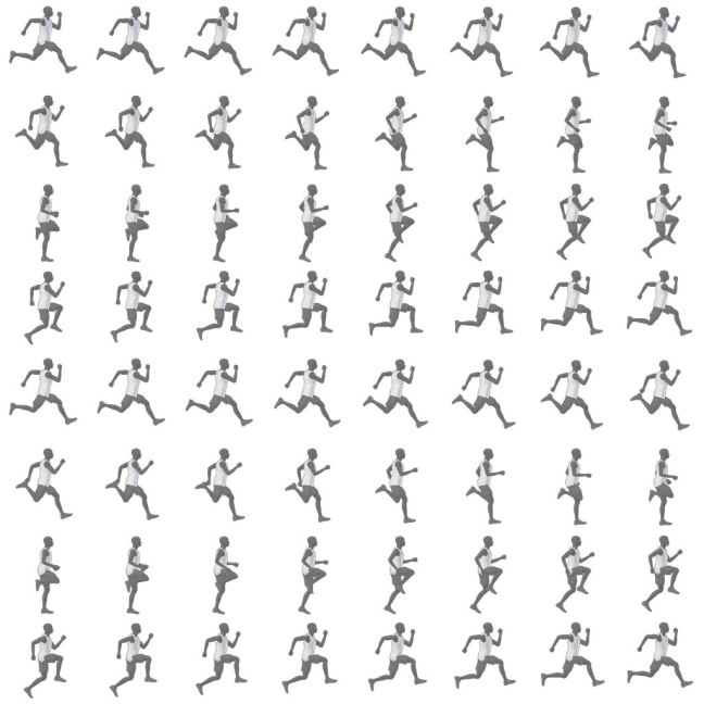
A ‘Flip Book’ node in UE4 is the way to create an animated texture using a Sprite-Sheet.
Its very simple to use:

  1. Import a Sprite Sheet texture containing the animation frames.
  2. In the UE4 Material, Create a Texture Object node, and set it’s Texture property to be the Sprite Sheet texture you imported.
  3. Create a Flip Book node and connect the Texture Object Node to its  Texture input.
  4. Connect numeric value constants to the Flip Book node’s Number of Rows and Number of Columns inputs to set the layout of the Sprite Sheet.
  5. Connect the outputs of the Flip Book node to the wanted material inputs.

Runner_Atlas

Untitled-1

The following example shows a way to create a custom Flip Book material to animate textures.
Q: Why would you do that???
A:
Well the truth is I created it without knowing there is a built-in option, and found out about the Flip Book node right after I finished my own.. 😀
But it’s also a useful example of locating tile coordinates within a plane..

Untitled-2.jpg


Create a richly colored metallic surface in UE4

Software:
Unreal Engine 4.18

One of the optical properties of many metallic surfaces is changing it’s color slightly as the surface viewing angle changes.
This effect can be simply created using a Fresnel node and a color-ramp texture.

Untitled-4

  1. Create a metallic material (metallic value of 1.0).
  2. Use an image editing software to create a linear color ramp texture (gradient) of the color change per viewing angle from left to right. like this example for a golden metal, and import it to your project.
    Ramp_Gold
  3. Add the ramp texture to the material Blueprint, and connect it to the material Base Color Input.
  4. Create a Fresnel node and set its Exponent value to 1.0 and its Base Reflect Fraction to a value of 0.0 so it will provide a linear angle blend value.
  5. Connect the Fresnel node’s output to the UVs input of the ramp texture node.
    * the reason the Fresnel node can be providing both the X and Y texture coordinates is that the texture’s Y dimension provides the same color for all values anyway.

Note:
When the Metallic property of an Unreal Engine material is set to 1.0, the material automatically simulates the metal’s color fading to white at parallel surface viewing angle (the sides) like it should.
So using a Color Ramp Texture like in this example creates an amplified effect.
* Simply put: You don’t have to have the Color Ramp fade to white on the right side of the texture..

Untitled-4

Untitled-3

UE4 – Material Fresnel Node

Software:
Unreal Engine 4.18

The UE4 Fresnel node is actually a “Facing Ratio” node (aka Perpendicular / Parallel) with some extra control.
It basically allows controlling material effects according to the incident angle the surface is viewed at, which is a hugely important feature for designing advanced material effects.

Untitled-3

Exponent:
The steepness of the value / angle curve.

Base Reflect Fraction:
The value at perpendicular angle.

Normal:
An option to connect World Space surface normals input to affect the output of the Fresnel node.
* Tangent Space normals must be converted to World Space by using a Transform Vector node.

Note:
A value of 1.0 for the Exponent parameter, and a value of 0.0 for the Base Reflect Fraction will produce a linear “Facing Ratio” (“Perpendicular / Parallel”) falloff blend.

Examples of different values:
Untitled-3
Untitled-4

More info:
https://docs.unrealengine.com/latest/INT/Engine/Rendering/Materials/HowTo/Fresnel/

Related posts:

  1. UE4 – basic architectural glazing material
  2. Understanding Fresnel reflections

UE4 – Material Transform Vector Node

Software:
Unreal Engine 4.18

The Transform Vector material node transform the supplied vector between different geometrical spaces according to your choice:

Untitled-4

Note:
This is useful in order to convert surface normals from Tangent Space to World Space to connect them as input to a Fresnel Node.

Basic architectural glazing material in UE4

Software:
Unreal Engine 4.18

  1. Create a new material, and double click it to edit it.
  2. In the Details panel, under Material, set Blend Mode to Translucent.
  3. In the Details panel, under Translucency, set Lighting Mode to Surface Translucency Volume.
  4. Set Base Color to White.
  5. Set Metallic to 1.
  6. Set Roughness to 0.
  7. Create a Fresnel node and connect it to the Opacity input.
  8. In the Fresnel node, set Base Reflect Fraction to control reflection amount in perpendicular surface viewing angle (front).
    * Note that its connected to Opacity, but since the material is basically a flat mirror, when it’s not purely transparent it will be reflective.
  9. In the Fresnel node, set Exponent to control the reflection amount falloff curve from perpendicular surface viewing angle (front) to parallel surface viewing angle (sides).
    * Higher values will create a steep falloff curve, resulting in less reflection in most viewing angles.

Untitled-3


Related:

  1. 3ds max & V-Ray to UE4 Datasmith workflow
  2. UE4 – Material Fresnel Node
  3. Understanding Fresnel Reflections